Halinski PzKpfw V Panther
Jim Nunn
Second article in the series
Photos by the Peter Crow and the Author
The Birth of the Panther:
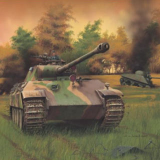
The beginnings of the Panther Project starts in 1935 when the German Army Weapons Department started development of a heavy tank in the 30 to 35 ton range to replace the PzKpfw IV. During 1938 to 1940 Several prototypes by Henschel, Porsche and MAN were produced some were converted to self-propelled guns and some of these prototypes saw service on the Russian front. The Tiger I was an outgrowth of the program.
Until 1941 there appeared to be no urgent need for medium/ heavy tank in the 35 ton range but at this time General Guderian came face to face with the Russian T-34 and realized that the PzKpfw IV was out gunned and under-armored when compared to this excellent Russian tank. Because of Guderian's report to the Armaments Ministry a committee was formed to study and develop a tank to counter the T-34
In November 1941 the Army Weapons Department issued the VK 3002 contract to Daimler-Benz and MAN for a 35-ton tank with sloping 60 mm frontal armor and 40 mm side armor and a top speed of 55 kph. The Daimler design VK 3002 () was a nearly exact copy of the T-34 using a diesel engine, rear drive and weighed 35 tons. The MAN VK 3002 (MAN) used a gasoline engine, Torsion bar suspension, and was driven by a front sprocket. The MAN prototype was a more traditional tank design then the Daimler-Benz design. The basic requirements for the MAN prototype were changed to 80 mm frontal armor and the weight was increased to 43 tons. Both tanks were to be fitted with the 75 mm L/48 (48 times the bore) gun.
In April 1942 the two prototypes were shown to Hitler and the German high command. Hitler preferred the Daimler-Benz design and suggested that the tank be fitted with the new Rheinmetall-Borsig 75 mm L/70 high velocity gun. An order for 200 tanks was awarded to Daimler-Benz but was later rescinded by the Panther design committee and then given to MAN. The first production prototypes were delivered in September 1942 and production was started in November 1942.
This month we will start construction of the interior of the Panther.
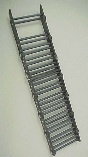
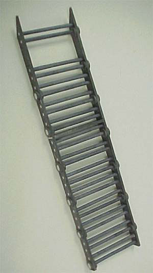
Working from the bottom up we start with part numbers 10-19 to assemble the torsion bar suspension.
The first assembly is a ladder like structure that is composed of two 1 mm wide strips representing the hull bottom stiffeners/torsion bar guides and torsion rods with a diameter of a little over 2 mm.
A similar smaller assembly is assembled for the engine compartment. |
 |
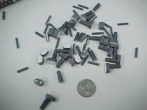 |
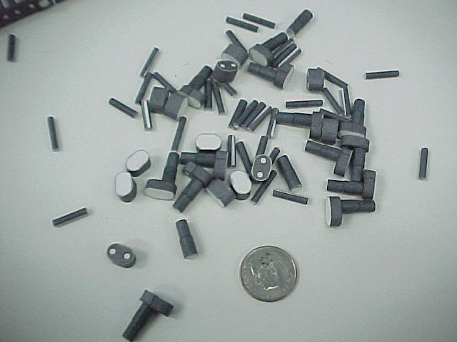
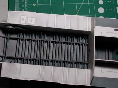
The assemblies are glued to the bottom of the hull making sure that they are equally spaced from the hull sides. Next we assemble the short torsion rods and assemble bearing boxes for the outer torsion bar assemblies. The bearing boxes are glued to the outer hull sides. Each of the shorter rods will have to be trimmed to fit between the bearing boxes and the center assembly. Rather then follow the indicated gluing positions for the rods I used the center rod as a guide to make sure that the torsion bar looked like one continuous rod across the bottom of the hull.
After rolling around 80 tubes I considered starting a second career making soda straws. |
|
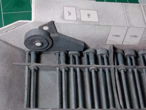
Next we assemble the transmission and brake assembles with parts numbered 20 to 45. The brake assemblies are glued to the outer hull sides. Surprisingly the backside of the control panels mounted on the transmission do not have a back cover and needed to be panted to match the transmission. |
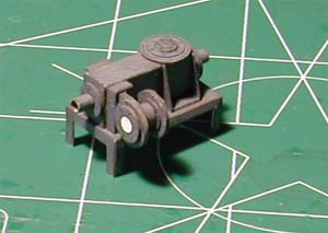 |
The next assembly is the turret traverse gearbox and we use parts 46 to 63 to make up the gearbox. |
|
when the part is finished being assembled any white paper that can be seen is painted with watercolor paints I have also added more weathering to the hull bottom and torsion bars.
We will discuss watercolor paints in the next article but I prefer them to marking pens and colored pencils. |
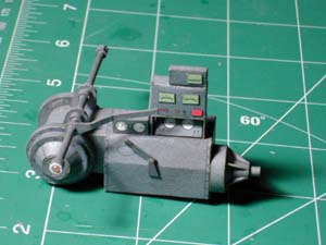
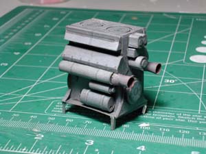
| Now we will tackle the engine. The engine is assembled from parts numbers 64 to 92.
At this point we find the first, and we hope the last, incorrect parts. Part number 69, the top of the engine is to narrow by 2 mm and Part number 77 is the base of the exhaust system and is composed of a tapered cone with a notch cut into one side to fit over the exhaust manifold. Do not cutout the notch as indicated, cutout the oppaset side of the notch. |
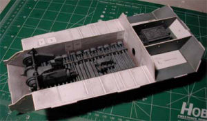 |
The photo shows the location of the various assemblies. I have not glued the engine, traverse gearbox or transmission in place I will wait until I am finished the drive shafts that connect these assembles to the engine so that the assemblies and drive shafts can be trimmed to get a good fit. |
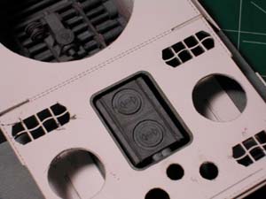 |
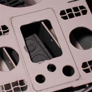
With all of the assemblies fitted in the hull I wanted to see how the engine would look through the engine hatch. As you can see in the photo all you can see of the engine is the top of the engine, all of the very nice detail is lost.
I decided that I would open up hull top and hull skin so that the engine compartment can be viewed. To get the location of where we will cut the hull top, I traced the shape of the engine compartment on the hull top through the rear of the hull. Measuring the size of the engine compartment on the outer skin I shortened the traced cutout by 1 mm on all sides. This will allow the hull skin to over lap the hull top so that we will get a good fit. |
 |
With the exception of the exhaust part and engine top all of the fits have been excellent. Due to the various thickness of backing card stock that could be used by the modeller I would expect to have to trim the torsion rods to get the best fit. |
Next month we will continue working on the interior.